To render images at interactive framerates, engines have to approximate the behaviour of real world phenomena – such as shadows – rather than simulating them. As real time rendering techniques continue to push towards photorealism, the cost of these approximations approaches the point of diminishing returns. Although traditionally seen as a complex offline process, ray tracing is becoming an increasingly viable alternative for effects that benefit from the visibility of surrounding objects.
When it comes to our PowerVR Ray Tracing hardware, the Tile Based Deferred Rendering rasterization functionality is tightly coupled with the units responsible for ray tracing. This creates an opportunity for ray tracing to be used as a complement to rasterized renders rather than an outright replacement. In this post, I’ll explain how to augment an OpenGL ES deferred lighting system with ray tracing.
Deferred lighting + ray tracing
G-buffer hybrid rendering is a technique we’ve used in most of our ray tracing demos as it’s proven to be an effective way to get the most out of PowerVR Ray Tracing hardware. The raster path of the GPU is used to render object data in screen space. This information is then used to initialize secondary rays emitted to the ray tracing hardware. By using one less ray per-pixel than a native ray tracer, applications can conserve the ray budget until the latter stages of the pipeline where it is needed most.
Of course, there’s another big benefit to this approach – it can piggy-back deferred lighting systems that already generate G-buffers!
Here are five steps to adding ray tracing to an OpenGL ES-based deferred lighting system:
Step 1: Update scene hierarchies (ray tracing)
Unlike a rasterized render, there are no draw calls in the ray tracing API. Instead, images are rendered each frame by emitting rays to a scene hierarchy acceleration structure containing world space object data. Hierarchies can be reused each frame if the objects within them do not need to change. When Component changes are required, the corresponding hierarchies must be rebuilt before the ray traced render is kicked.
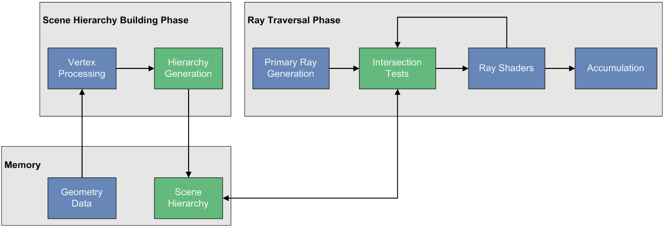 Ray tracing pipeline – scene hierarchy generation
In the extension nomenclature, there are a few important terms that describe the division of work here:
|
Term |
Description |
|
Component |
A 3D object and associated material properties (e.g. buffers & shaders) |
|
Component Group |
Hierarchical acceleration structure used for efficient ray-box and ray-triangle tests. Built from Components or by merging Component Groups |
|
Scene Array |
An array of Component Group handles. Rays must be emitted to a single element of this array |
When a Component Group is built, input Components are transformed into world space by the vertex shader programs bound to them. Transformed data is then streamed to the fixed-function Scene Hierarchy Generator unit to generate the scene hierarchy. It’s worth noting that Component Group builds invalidate the hierarchy’s previous contents, so a list of required Components must be passed to each build.
As reuse is possible, Component Groups can be created and built at startup for unchanging objects such as buildings and terrain. Additional Component Groups can be generated for objects that are modified each frame. To avoid pipeline stalls, dynamic Component Groups can be multi-buffered so rays can traverse one hierarchy while an application kicks a build for another. Once built, Component Groups can be inexpensively merged before ray dispatch.
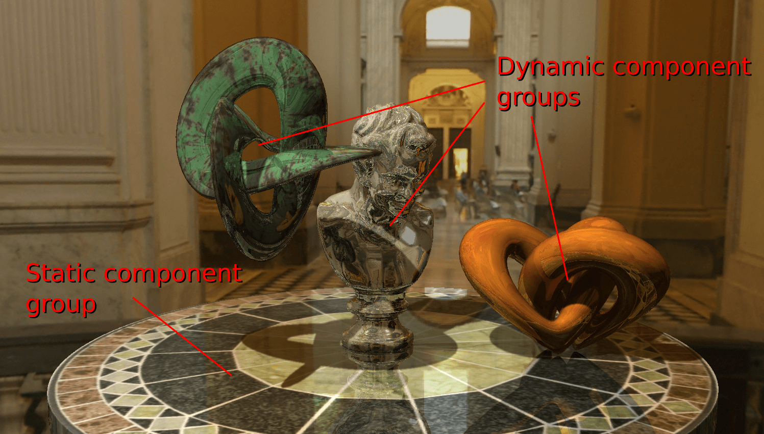 Dynamic and static Component Groups (see the full demo video on YouTube)
In a typical application with dynamic objects, the following steps must be taken:
- Update dynamic Components
- Modify attributes and buffers as necessary
- Build the dynamic Component Group
- Select the dynamic “back buffer”. Kick a build with a list of Components
- Merge Component Groups
- Merge the latest dynamic and static groups before rays are dispatched
- Explicitly synchronize builds. Component Groups must not be modified between the merge API call and the end of the ray traced render
Once builds have been kicked, the application can move to the next task.
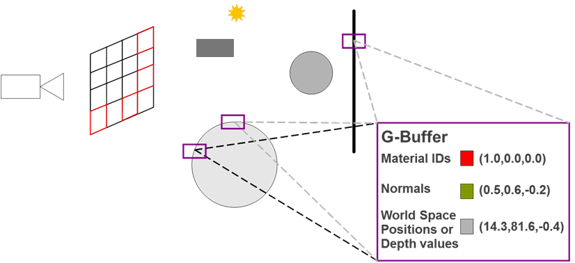
Step 2: Build the G-buffer (rasterization)
In this step, the rasterization pipeline of the GPU is used to render screen space object data into a G-buffer. The information stored will depend on inputs required by the lighting and ray tracing passes, but commonly includes world space position, normals, material IDs and albedo.
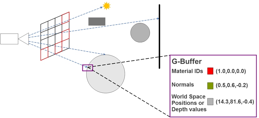 Building the G-buffer
Unlike the ray tracer, the rasterized pipeline requires objects to be transformed to camera space every frame. An application must submit draws for objects within the view frustum to render the G-buffer.
As PowerVR is a tile-based architecture and the reference graphics driver exposes the EXT_shader_pixel_local_storage extension, G-buffer data can be kept on-chip instead of performing bandwidth intensive texture writes and reads. This reduces the latency and power consumption of these operations.
Step 3: Deferred lighting (rasterization)
Once the G-buffer is rendered, screen-space lighting can be calculated. To avoid writing this data off-chip, it can be written to Pixel Local Storage and then read by the Frame Shader.
 Hybrid G-buffer lighting
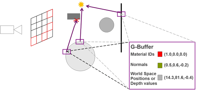
Step 4: Emit primary rays and calculate ray – object intersection (ray tracing)
Step 4a: Emit primary rays (ray tracing)
|
Term |
Description |
|
Frame Shader |
A shader stage for emitting primary rays. Frame shaders instances are executed for application defined width x height elements |
 Initializing rays with G-buffer data
In the OpenGL ES ray tracing API, rays are emitted via a programmable stage called the Frame Shader. In a G-buffer hybrid renderer, a frame shader instance runs for each G-buffer pixel. The object data stored in the G-buffer is used to initialize zero-to-many rays per-pixel.
The gl_SceneIMG built-in allows a Frame Shader instance to specify which Scene Array element the rays will be dispatched to. In dynamically updating scenes, rays must be dispatched to the latest merged dynamic + static Component Group.
Like compute shaders, Frame Shaders do not have required outputs. They can optionally write data to buffers and images. Also – importantly – they can emit rays!
The extension includes a new image add function and a qualifier to mark uniform image variables as accumulate only. These features enable the hardware’s Frame Accumulator Cache to optimize image writes.
Step 4b: Ray – object intersection (ray tracing)
|
Term |
Description |
| Ray Shader | A shader stage executed when a ray intersects a primitive. Ray shaders can be bound to a Component |
 Ray – light intersection
Once dispatched, rays will traverse the scene hierarchy to perform ray-box and ray-triangle intersection tests. When a ray-triangle intersection occurs, the Ray Shader bound to the intersected object will be executed. A Ray Shader has access to ray data such as its point of origin and its direction, along with user defined data attached to the ray. It also has access to un-interpolated data at the point of intersection, such as texture coordinates and normals. Intersection barycentric coordinates are provided along with interpolation helper functions, giving the user complete control over how interpolation is performed. Like Frame Shaders, Ray Shaders have no required outputs and can optionally write to buffers, images or the render’s accumulation buffer. They can also emit more rays!
Step 5: Post-processing (rasterization)
Once the ray traced render completes, post-process passes can be used to filter the rendered image and apply the usual host of 3D screen-space effects (motion blur, depth of field, vignette etc.).
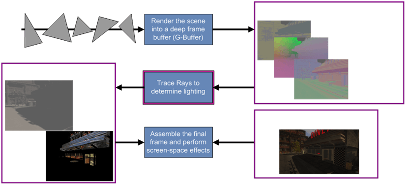
Summary
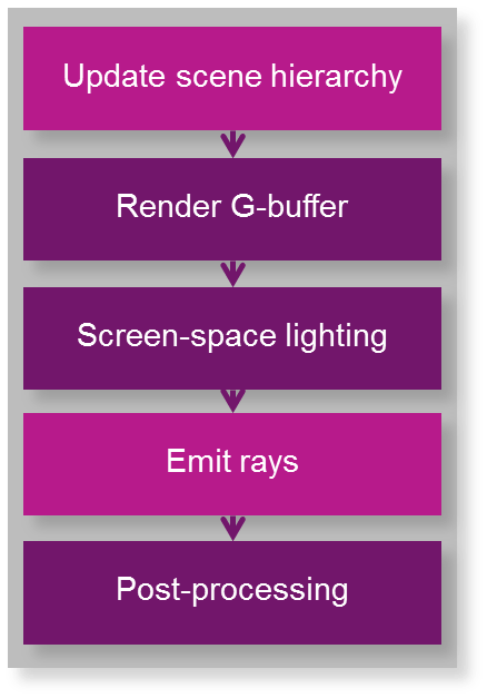 Generic G-Buffer hybrid rendering pipeline
With G-buffer hybrid rendering, OpenGL ES deferred lighting systems can be easily extended to benefit from ray tracing. In future posts we will detail how the technique can be used to augment renders with specific ray traced effects, such as screen space soft shadows. If you have any questions about the post, please leave a comment below!