- 14 January 2022
- Benjamin Anuworakarn
Shadows play an important role in conveying realism to the user and to ground objects in the scene of any visual graphics experience. Yet, they have long remained one of the most difficult features to accomplish at both speed and quality in real-time applications. As hardware improves and hardware-accelerated ray tracing techniques become more prevalent, developers have gained the ability to render shadows more accurately and quickly than ever before. Here at Imagination, we believe in the potential of ray tracing for the future of real-time rendering, and are always looking to push the boundaries of what’s possible.
This blog post will cover a brief overview of how to generate a fully ray-traced scene with hard shadows, as well as a high-level overview of the Khronos Vulkan ray tracing extension. For those who have read our previous highlight on Ambient Occlusion, this will serve as a great follow-up, going from lighting techniques entirely through rasterization to now using full ray tracing. Just as with our Ambient Occlusion post, there is a code example of fully ray-traced hard shadows in our PowerVR SDK, which you can explore at your own leisure.
Current Shadowing Techniques
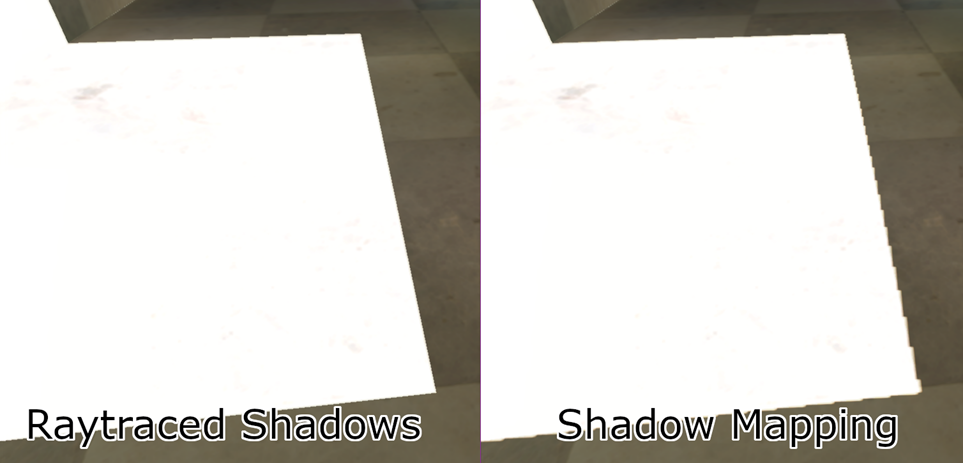
Over the past decade, the prevalent method for rendering shadows in real-time has been through the use of shadow mapping. This is where the scene is rendered again from the light source’s perspective into an off-screen depth buffer, known as a shadow map, which is then sampled during the shading pass to compute visibility using a depth comparison. While this method has been used successfully on many applications, it has a few shortcomings.
The most common issue is shadow aliasing – this is where the shadow map’s resolution is too low, which results in having blocky shadows. While this can be fixed by using a higher resolution shadow map, this increases the memory footprint and bandwidth utilisation, which can negatively affect performance – especially on mobile devices. Even with a higher resolution shadow map, certain micro-details are very difficult to preserve, which require follow-up screen-space shadows passes to refine. However, when using ray tracing, you can allocate one ray per pixel on the screen, which will result in pixel-perfect hard shadows.

The Ray Tracing Pipeline
Ray Generation
When the command buffer makes a call to vkCmdTraceRaysKHR, a user-defined number of ray generation shaders are invoked for the currently bound ray tracing pipeline. The command to trace rays allows developers to set various parameters for the threads dispatched. Our demo is fully ray-traced, meaning that it would be best to dispatch one ray generation shader thread per pixel on the screen.
Each invocation of the ray generation shader will have to assign the variables required to launch the primary rays into the scene. A ray needs to have an origin (the viewpoint) and a direction of travel. The origin can be calculated by applying the inverse view matrix to (0,0,0,1). To calculate direction, the screen-space location of the current pixel is required. The dispatch coordinates can be queried from the ray generation shader using gl_LaunchIDEXT. Using this extension built-in, the screen-space coordinates and ray direction can be calculated as follows:
const vec2 pixelCenter = vec2(gl_LaunchIDEXT.xy) + vec2(0.5);
const vec2 inUV = pixelCenter / vec2(gl_LaunchSizeEXT.xy);
vec2 screenspace = inUV * 2.0 - 1.0;

vec4 target = mInvProjectionMatrix * vec4(screenspace.xy, 1, 1);
vec4 direction = mInvViewMatrix * vec4(normalize(target.xyz), 0);
From here, we can use the traceRayEXT function to fire the primary ray into the scene. It will then traverse the acceleration structure, where it will either hit or miss geometry in the scene and call the respective shader group. The shader group executed will depend on what it hits, and will store the colour of the pixel inside a payload structure. The miss shader simply sets the colour of the ray at a hard-coded clear colour.
Hit Group Shader
Once a ray has collided with an object the scene, the hit shader is executed. The model data such as the vertex buffer, index buffer, and materials are all attached to the hit group shader. The ray tracing extensions allow us to get the instance ID of the object hit. In this demo, each model is unique so the instance ID corresponds directly to the model ID. The model ID can be used to look up the aforementioned buffers.
// Since each object is unique in this scene, instance ID is enough to identify which buffers to look up
uint objID = gl_InstanceID;

// indices of the triangle we hit
ivec3 ind = ivec3(indices[nonuniformEXT(objID)].i[3 * gl_PrimitiveID + 0], //
    indices[nonuniformEXT(objID)].i[3 * gl_PrimitiveID + 1], //
    indices[nonuniformEXT(objID)].i[3 * gl_PrimitiveID + 2]); //

// Vertices of the hit triangle
Vertex v0 = vertices[nonuniformEXT(objID)].v[ind.x];
Vertex v1 = vertices[nonuniformEXT(objID)].v[ind.y];
Vertex v2 = vertices[nonuniformEXT(objID)].v[ind.z];
gl_PrimitiveID can be used to tell us which indices to use to look up the vertices hit, and then interpolate between them using the barycentric interpolation coefficients from a variable of type hitAttributeEXT called attrib declared globally in the hit shader. We then use the world matrix to transition the interpolated vertex values into world space and rotate the normal values.
// Get the interpolation coefficients
const vec3 barycentrics = vec3(1.0 - attribs.x - attribs.y, attribs.x, attribs.y);

// Interpolate the position and normal vector for this ray
vec4 modelNormal = vec4(v0.nrm * barycentrics.x + v1.nrm * barycentrics.y + v2.nrm * barycentrics.z, 1.0);
vec4 modelPos = vec4(v0.pos * barycentrics.x + v1.pos * barycentrics.y + v2.pos * barycentrics.z, 1.0);

// Transform the position and normal vectors from model space to world space
mat4 worldTransform = transforms[nonuniformEXT(objID)];
vec3 worldPos = (worldTransform * modelPos).xyz;

// Don't translate the normal vector, only rotate and scale
mat3 worldRotate = mat3(worldTransform[0].xyz, worldTransform[1].xyz, worldTransform[2].xyz);
vec3 worldNormal = worldRotate * modelNormal.xyz;
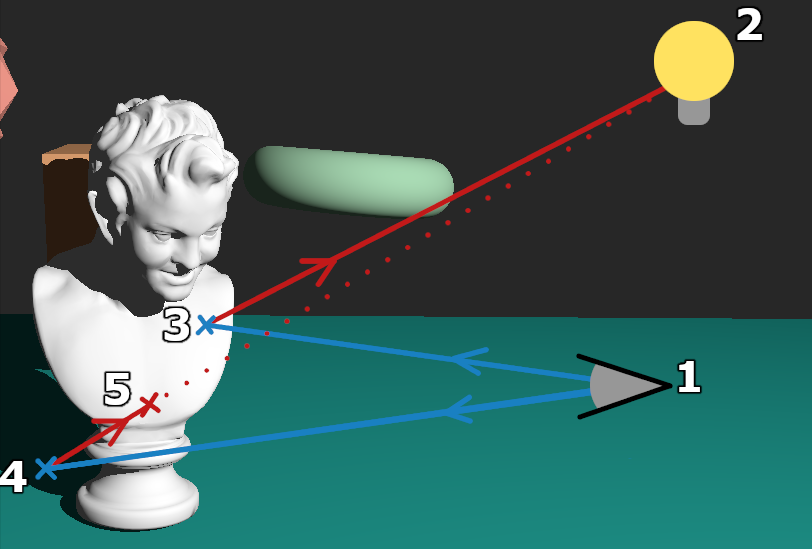
Using the normal and world position of the hit point, we can calculate the Phong lighting component of the ray against the static light source in our scene. Then, we fire another ray from that point towards the light source using a new hit and miss group. We can set the max length of the secondary ray to be the distance between the hit point and the light source. If the ray collides with anything in the acceleration structure in that distance, we can conclude that there is an object between the hit point and the light source, and that the point is thus in shadow. If the secondary ray does not hit anything within the distance set, the ray miss shader executes, and we can assume the point is not in shadow.

In this diagram we can see two examples. The rays launch from the viewport (1), the first ray hits at point 3, and a second ray is launched which does not hit any geometry on its way to the light source. The second ray from the viewpoint hits at point 4, but then collides again at point 5 on its way to the light source. Thus, we can conclude that point 4 is in shadow but point 3 is not.
Optimisations
While ray-traced shadows provide more fidelity than the traditional methods, they are still not exactly perfect. The first primary drawback is that ray tracing algorithms are notably heavier in terms of computation cost, and thus require specific, dedicated hardware in order to be feasible in real-time applications. Besides this, there are a few different optimisations that can be taken to improve the technique outlined here.
Shadowing Checks
We can reduce the number of secondary rays fired in the first hit group used to check for hard shadows; this is done by first checking the Phong lighting component that was computed. If the lighting component is already 0 because the surface is facing away from the light source, then there is no point in checking for hard shadows, because the point is already in darkness.
This reduces the ray budget from roughly 1.8 times the number of pixels on the screen down to around 1.5 times. This is obviously dependant on the scene and the objects within, as it changes with the proportion of primary rays that miss the scene and the proportion of primary rays that pass or fail the shadowing check.
Hybrid Rendering
In general, ray tracing cores are going to be slower than the traditional rasterization pipeline (at least, for now). There are a few possible reasons for this, but the main one is that ray tracing hardware is still relatively new, so GPUs still have yet to dedicate much more space to it compared to rasterization. This means that it’s possible to compute a standard G buffer and use the positions attachment to locate the position from which to fire the shadow check rays. G buffers were covered in our Ambient Occlusion post, so do take a look at that if you haven’t already. In short terms, a G Buffer can replace the primary rays, thus resulting in better task overlap and a smaller ray budget.
Closing
While fully ray traced hard shadows may not be the optimal solution at the current time of writing, they do still provide a level of detail and accuracy that is hard to mimic with traditional pipelines. As always, we highly recommend taking a look at the PowerVR SDK and its code examples to see the exact mechanisms of how we accomplish these techniques and implement these algorithms. We’re also always an email away, either through the support portal or the Forums.
If you’re interested in finding out more about various graphics techniques, take a look at our Documentation Website, or explore our other code examples in the SDK Github.
Until next time!


