- 08 June 2017
- Benjamin Anuworakarn
This blog post introduces GRLAA (GRadient Line Anti-Aliasing), a relatively simple and efficient method designed to cope with aliased lines, which can often crop up in automotive navigation applications.
In the discipline of signal processing, there is a specific sampling frequency called the Nyquist frequency. When sampling a signal at a frequency lower than the Nyquist frequency, the signal reconstructed from these samples is different to the original. The difference between the original and the reconstructed signals manifests as artefacts. This effect is called “aliasing”.
Two of the most common manifestations of aliasing in computer graphics are discussed here. The first is “jaggies” (Figure 1) where what is intended to be a diagonal straight line appears as a jagged staircase. This is introduced by the “rasterizer stage” of the graphics card rendering “in between” pixels as either on or off.
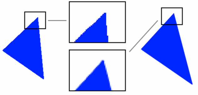
The second is sampling aliasing. This is when a high frequency (rapidly changing) texture is being used to render something in the distance, such as the checkerboard pattern in Figure 2, and appears to create visible artefacts known as moiré patterns.

There are several algorithms used to combat the amount of visible aliasing and get rid of the staircase artefacts. However, these algorithms might incur a moderate performance cost depending on the hardware to which you are deploying.
- Super-sampling anti-aliasing (SSAA). This is a brute-force technique that renders the whole scene in a resolution that is an integer multiple (x2, x4) than the final one, and then down samples the whole framebuffer to produce the desired final resolution. The result is excellent quality and improves both jaggies and texture sampling artefacts, but the technique is obviously extremely expensive. The costs of rendering – including raster ops, fragment ops and associated bandwidth – are multiplied by the square of the resolution multiplier i.e. x4 for x2 SSAA, x16 for x4 etc
- Multi-sampling anti-aliasing (MSAA). This technique increases the number of samples taken per pixel by rendering the image to a buffer, which is able to store multiple samples per pixel. It then resolves that buffer to produce an output that matches the viewport resolution. This is very efficient on PowerVR hardware as the resolve is performed on-chip, saving precious memory bandwidth. MSAA improves jaggies but not sampling artefacts.
- Shader-based techniques such as fast approximate anti-aliasing (FXAA) or sub-pixel morphological anti-aliasing (SMAA). Both of these techniques use analytics to detect and blur sharp geometric features. They are also post processing algorithms which are performed in screen space, and generally, have a fixed cost (a single full-screen pass) but require more memory bandwidth, which is usually at a premium on mobile and embedded devices.
GRadient Line Anti-Aliasing Technique Overview
Gerry Raptis, our PowerVR SDK team lead, came up with this GRLAA technique to improve the look of the roads of our navigation demo.
GRLAA greatly improves the visual quality of the edges of the road geometry at a low computational cost. In addition, it makes it trivial to add the outlines of the road. Outlines improve the look of road edges and act as a visual aid for users, enabling them to more clearly distinguish the road boundaries.
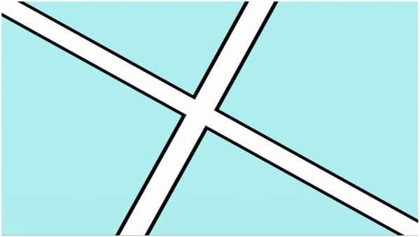
The general idea behind this approach is to render the centre of the road opaque, and then gradually introduce transparency for a percentage of the pixels that are near or on the edge of the road’s geometry.
The alpha of any particular fragment is based on two values. The first value is the distance between the fragment and the edge of the road. The second is the rate of change of this distance; this is also known as its gradient or, more formally, its partial derivatives.
The RGB colour of the fragment is determined by performing an interpolation between the value 0, 0, 0 to produce a solid black outline (or another outline colour) and the road’s flat colour, which is passed to the fragment shader as a uniform. All that is based on the interpolant t, which is derived from the relative distance and rate of change calculations. In the next section, there will be more detail on how to derive these values and why they are significant to the GRLAA technique.
It might be worth noting that the algorithm, in its current form, can only work for geometry that represents an object with a known width, such as a road, line etc.
Analysis of the GRLAA technique
In order to correctly apply the appropriate level of blending, the algorithm needs to know how far it is from the edges of the road as this affects the intensity of the blending. This means that for each vertex in the data set there must be some extra vertex data appended, which must be one of two constant values: -1 or 1. The assigned value should alternate between the odd and even vertices, this means that one edge of the road will receive the base value of -1 and the other will receive the base value of 1. This data will be uploaded to the graphics hardware as vertex data for use in the fragment shader to help calculate the final alpha value.
The base values assigned to the vertices distinguish between each edge of the road i.e. left and right-hand-sides. As the vertex data is being used in the fragment shader they will be automatically interpolated by the hardware.
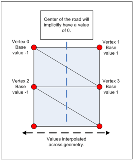
The interpolated base values are then used to calculate the relative distance from the current fragment to the edge of the road. For example, the centre of the road is the furthest a fragment can be from either edge, meaning its relative distance will be 1, and will effectively receive no blending. As a fragment moves closer to the edge of the road, its relative distance will approach 0 and as a result, it will gradually receive more blending.
float distance = 1.0 – abs(roadBaseVal);
Now that the relative distance from the edge of the road relative to the road width is known, it needs to be determined how much of the road outline must be blended. The second part of the algorithm involves calculating what percentage of the fragments need to be blended.
The base interpolated value from the vertex data is used as a parameter to the standard GLSL partial derivative (gradient) functions. The functions ‘dFdX’ and ‘dFdY’ are typically used to calculate the rate of change of a given value in screen space along the X and Y axis respectively – this is typically determined over a small grid (2 x 2) of fragments.
This calculation gives the rate of change of the relative distance from the current fragment to the edge of the road, based on the partial derivative of the current fragment with relation to its neighbouring fragments. Based on this rate of change for any given fragment it is possible to calculate the appropriate alpha value for it. The resulting value determines the percentage of fragments that define the edges of the road, and consequently how many fragments overall will be blended in order to give a smooth outline.
#define ANTIALIAS_STRENGTH 2. // Constant affects how much AA will be applied, a higher value //will increase blurring at the cost of reduced detail, while a lower value will reduce the //amount of blurring at the cost of more aliasing.
float blend_range = ANTIALIAS_STRENGTH * sqrt(dFdx(roadBaseVal) * dFdx(roadBaseVal) + dFdy(roadBaseVal) * dFdy(roadBaseVal));
float blend_halfrng = 0.5 * blend_range;
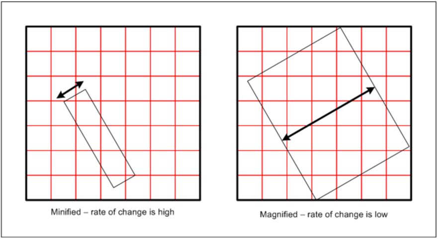
This rate of change value is very important as it enables the algorithm to be completely independent of the road’s scale and size on the screen. Using the partial derivative functions makes it possible to determine whether the object is taking up a larger or smaller percentage of the screen, for example:
- If the object is small on the screen (‘zoomed out’) the number of pixels needed to blend in order to achieve a smooth edge equate to a larger percentage of the total number of pixels that define the road geometry. This is because the rate of change will be high, as the base values will be interpolated over a small number of fragments. As a result, it will start blending fragments which are further from the edge of the road. If a smaller percentage of fragments were blended, jaggies would start appearing.
- Conversely, if the object is large on the screen (‘zoomed in’) then the pixels that are needed to blend are a small percentage of the total number of pixels that define the road geometry. This is because the rate of change will be low, as the base values will be interpolated over many fragments. As a result, it will start blending fragments which are closer to the edge of the road. If a larger than needed percentage of fragments were blended, the road would start to appear blurry.
With all the components in place, the final colour of the fragment can be calculated. The RGB component is calculated by performing an interpolation between the outline colour (in this case simply black) and the colour of the road (passed in via a uniform) based on the interpolant. The interpolant is derived from the relative distance and rate of change. The alpha component is calculated in a similar way, but does not require any interpolation.
#define OUTLINE_WIDTH 0.25 //How large our outline will be relative to the road width
float outline_distance = clamp(((distance – OUTLINE_WIDTH – blend_halfrng) / blend_range) + 0.5, 0.0, 1.0);
float blend_distance = clamp(((distance – blend_halfrng) / blend_range) + 0.5, 0.0, 1.0);
oColour.rgb = mix(vec3(0.0, 0.0, 0.0), roadColour.rgb, outline_distance);
oColour.a = blend_distance;
The main advantage that GRLAA has compared to previous, texture-based (luminance-alpha maps) anti-aliasing methods is that there is no reliance on mip-maps. With a texture-based approach, it can be limited in the amount of anti-aliasing it can do when the geometry is minified, since it is based on mip-maps. The algorithm discussed in this blog has absolutely no problem with handling geometry of any scale; it is capable of producing exceptionally crisp, high-quality anti-aliased outlines that are completely independent of the object’s scale and orientation.
The second advantage is that no textures are required by the algorithm, which might help to reduce the overall memory bandwidth for the entire application. This is great news, as it may free up some memory bandwidth potentially for other techniques that are texture hungry.
Finally, this approach is still relatively cheap in terms of cycle count and thus will not significantly add computational overhead. We measured an average of ~20 cycles to execute the entire shader. The use of medium precision may also reduce cycle count further depending on the graphics core you are running this on.
To keep up to date with everything PowerVR follows Imagination on social media at @ImaginationTech, LinkedIn and Facebook.


