- 15 June 2016
- Imagination Technologies
In my last blog post I offered a solution to successfully reduce latency in VR by using single buffer strip rendering. I mentioned that the graphics requirements for VR are quite high because the GPU has to do a lot more work compared to a traditional mobile application.
One reason for the increased workload is that we have to render the content twice (once for each eye). Another reason is the barrel distortion filter which gets applied to the final render by the GPU (again for each eye). This puts a lot of pressure on the graphics processor and we need to think about how we can reduce this pressure.
Why use lenses?
Considering how powerful mobile devices are nowadays, you may ask: why do we need to do these old school optical tricks in the first place?
There are two main reasons why VR headsets uses lenses:
- The lenses increase the field of view
- The lenses make it possible to have the screen so close to your eyes
For example, if the screen of your phone is 11.5 cm long by 6.5 cm wide, then horizontally you have 5.75 cm available per eye. Given that the screen is very close to your face, this isn’t nearly enough to cover the field of view of the human eye. Putting a lens between the screen and the eye will increase the field of view considerably – this is true for both the horizontal and vertical view.
By using lenses, we can make the virtual world look bigger than it actually is.
Secondly, lenses allow the user to comfortably look at a screen that is very close to their eyes, creating the effect of the screen being much further away than it really is.
Obviously this also has some downsides. Because of the distortion, some parts of the image will be compressed and therefore lose information; other parts are blown up which means we need content with a higher resolution. Lenses can also introduce chromatic aberration which needs to be corrected, too.
Barrel distortion
To correct the barrel distortion effect, we need to apply a reverse transformation so that the light emitted by the screen looks correct to the human brain. How this transformation is done depends on the physical lens design.
In VR, lens designs can become pretty complicated. Looking at the Oculus Rift CV1 they did a great job of optimizing the design for the VR use case. Obviously all these design decisions influence the math you need to do to the correct the image.
One common method for barrel distortion is using Brown’s distortion model. There are other models available for the distortion – like using a polynomial function or a spline. One common problem with most of them is that creating the reverse function is non-trival. To keep things simple we will use the following model for the barrel distortion where the inverse can be calculated:

Alpha defines the amount of distortion we want to apply and is defined by the theoretical lens design. The input values x and y in p are normalized between [-1, +1].
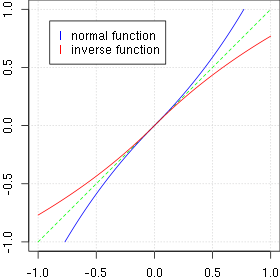
Profile of the normal and inverse distortion function for p(x, 0) and alpha=0.3
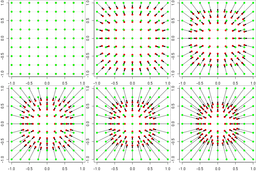
Animation of the barrel distortion with increasing alpha
Pixel based vs. mesh based correction
One approach is correcting the final render in a post processing fragment shader just before showing the final image. Let’s assume our VR content is rendered into one FBO per eye. Using OpenGL ES 3.0, the vertex shader and the fragment shader look something like this:
#version 300 es
in highp vec4 posVtx;
uniform mat4 mvpM;

void main(void)
{
 gl_Position = mvpM * posVtx;
}
#version 300 es
in highp vec2 texFrg;
out highp vec4 frgCol;
uniform highp vec2 centre;
uniform highp sampler2D texSampler;

void main(void)
{
 highp vec4 col = vec4(0.0, 0.0, 0.0, 1.0); /* base colour */
 highp float alpha = 0.2; /* lens parameter */
 /* Left/Right eye are slightly off centre */
 /* Normalize to [-1, 1] and put the centre to "centre" */
 highp vec2 p1 = vec2(2.0 * texFrg - 1.0) - centre;
 /* Transform */
 highp vec2 p2 = p1 / (1.0 - alpha * length(p1));
 /* Back to [0, 1] */
 p2 = (p2 + centre + 1.0) * 0.5;
 if (all(greaterThanEqual(p2, vec2(0.0))) &&
     all(lessThanEqual(p2, vec2(1.0))))
 {
  col = texture(texSampler, p2);
 }
 frgCol = col;
}
The centre allows for moving the centre of the distortion slightly out of the middle of the FBO, as normally the lens is not exactly centred to the left or right part of the screen.
Doing it this way is the most accurate approach we can use to calculate the distortion. Unfortunately it is also very expensive in terms of GPU usage. The vertex shader runs quickly since we only have to process six points (two triangles to output a rectangle). On the other side, the fragment shader has to do the transformation for every pixel on the screen. For a 1920 x 1080 pixel display this becomes 2073600 calculations and texture lookups.
Surely we can do better! Every programmer knows the key to good performance is pre-calculation and approximation. If you look at the content produced by any game out their today you will see they are full of approximations. Just take shadow calculations like cascaded shadow maps. Although this will massively improve in the future with the help of ray tracing.
Looking at the numbers above, it becomes clear we need to move the transformation out of the fragment shader. Instead of having one rectangle for displaying the FBO, we can use multiple rectangles that are connected and make up a mesh. If we now pre-transform this mesh, we get something looking like this:
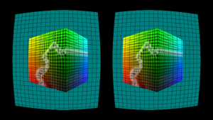
The advantage of this method is that we only have to do this once at initialization time; because the lens parameters don’t change over time, we can reuse the mesh on every frame. This makes up our first part of the optimization – the pre-calculation.
The second part is the approximation: in this case, it is defined by the mesh resolution. Everything between the mesh points will be interpolated. Having a smaller mesh resolution will produce an image with higher quality; having a bigger mesh resolution will be faster. So what are the savings by using a mesh? Using a 32 pixel mesh results in the following for our 1920 x 1080 pixel display:
(1920, 1080) / 32 = (60, 33.75)
We therefore have 2040 rectangles with 12240 points making up the vertices. The vertex shader will process 12240 points instead of 6. However, the same vertex shader as above can be used. The fragment shader can be reduced to the following:
#version 300 es
in highp vec2 texFrg;
out highp vec4 frgCol;
uniform highp sampler2D texSampler;

void main(void)
{
 highp vec4 col = vec4(0.0, 0.0, 0.0, 1.0); /* base colour */
 if (all(greaterThanEqual(texFrg, vec2(0.0))) &&
     all(lessThanEqual(texFrg, vec2(1.0))))
 {
  col = texture(texSampler, texFrg);
 }
 frgCol = col;
}
This will still do the texture lookups, but will avoid doing the transformations. We save a lot of processing power and on higher resolution displays the savings will be even bigger. However, on PowerVR GPUs there is another advantage. Because the vertex shader runs in the TA phase (you can read about the PowerVR architecture) it will run independently of the 3D phase where the rasterization happens and therefore the fragment shader is executed. If your content is fill rate limited, this will give you some more head room in making sure you finish your content render on time. Here I have summarized the savings again for our Full HD display example:
| Vertex Shader | Fragment Shader | Sum Approx. Shader Cycle Count | ||||
|---|---|---|---|---|---|---|
| MVP Multiplications | Aprx. Shader Cycle Count | Transformations | Tex Lookups | Approx. Shader Cycle Count | ||
| Pixel based | 6 | 9 | 2073600 | 2073600 | 22 | 45619254 |
| Mesh based | 12240 | 9 | 0 | 2073600 | 12 |
24993360 |
Quality assessment
If you look at the left part of the cube when the rotation pauses you can see how it follows the mesh. Between the edge points of a rectangle the texture lookup is simply linear interpolated. Another problem is that animations can start to wobble because they don’t smoothly follow the curve of the distortion. So we can already decide that 160 pixels are not good enough. But let’s look at a static image and compare it to the output of the transformation in the fragment shader. First I created the forward transformed image (which was done in software, not with the help of the GPU) of every output image. That is, the output when using the fragment shader only, a mesh size of 32px and a mesh size of 160px. I also created the difference image of those forward transformed images against the original untransformed output you see in the top left:
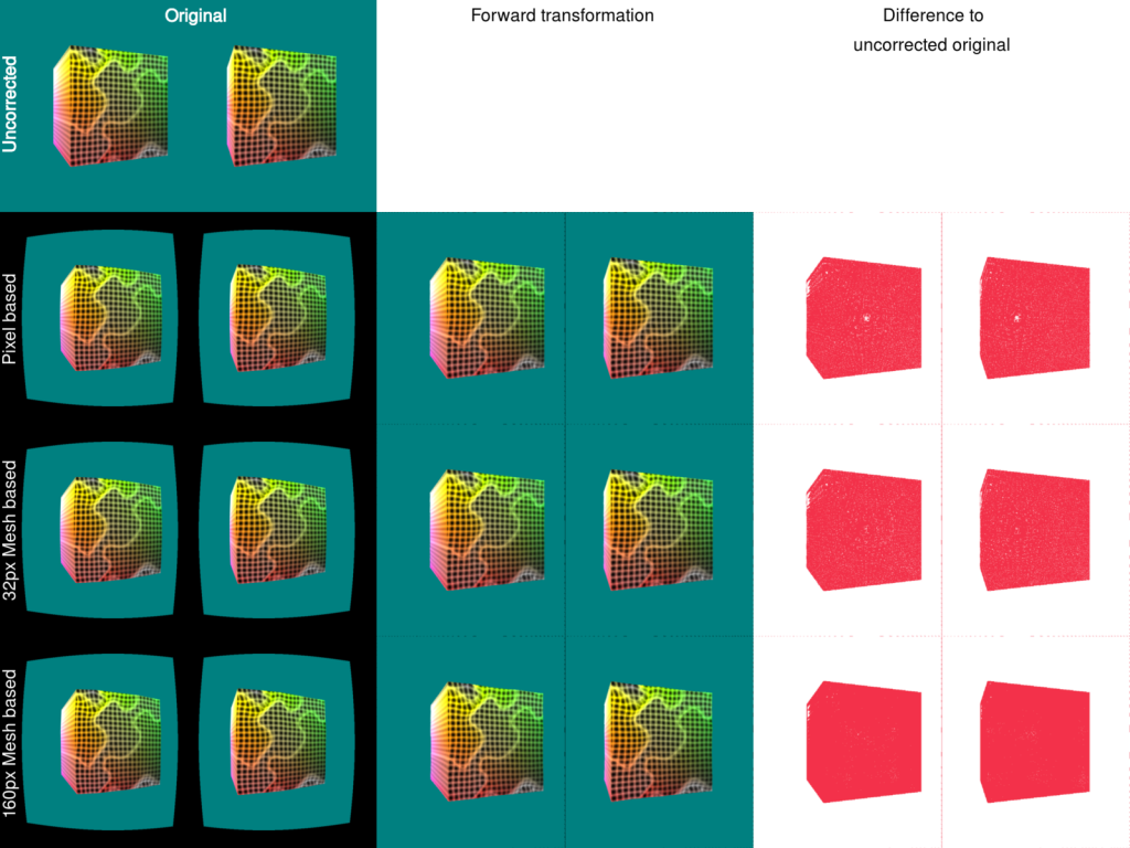 Image quality comparison (Click for a larger view)
You notice that you get more red in the difference images the further down the list you go. But let’s express this in a number. For image comparison of video codecs the PSNR is the known standard. By using some ImageMagick magic and calculating the difference image as well the PSNR we get this:
| Original vs.
pixel based |
Original vs. 32px mesh based |
Original vs. 160px mesh based |
|
|---|---|---|---|
| red | 35.772 | 35.6566 | 20.5676 |
| green | 32.4456 | 32.2582 | 21.9138 |
| blue | 33.1863 | 33.1274 | 25.969 |
| all | 34.8336 | 34.7073 | 23.5308 |
Higher PSNRs mean greater equality between the two images. We can clearly see that using 32px as the parameter for the mesh results in images very close to the images generated by using the fragment shader.
Conclusion
Doing lens corrections is a vital part of the VR pipeline. By using the right techniques we are able to reduce the GPU requirements for this specific part while keeping the image quality high. This enables the application to create richer content or the device to save power by shortening the time the GPU has to be awake.


